Rebuilding and Installing a "1939" Transmission
Part 5 - Installing the new transmission
Things should have been down hill from here, except various mistakes from earlier weren't obvious until this point. These were the rear transmission mount/bearing cover, and the clutch linkage.
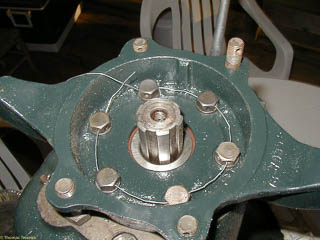
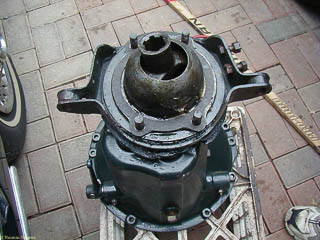
The rear bearing is held in place with a cover that also serves as the rear transmission mount. It bolts into place, and the bolt heads have holes for safety wire.
NOTE: This is not the way to install safety wire for an aircraft or for racing.
The proper way to install safety wire would have twisted strands of wire between the bolt heads, but I didn't discover this until researching this write-up. However, this is how the wires had been installed when I took the transmission
apart — a single, somewhat heavier wire threaded through the bolt heads. I did use stainless steel wire.
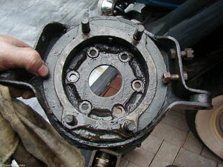
But that's not the mistake that caused problems at the time. This transmission mount is very different from the one that was in the truck: the biggest problem is lack of a bracket for the parking brake. It was no big deal to remove
the transmission mount from the old transmission and move it over to the new.
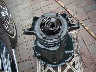
I decided to use the universal joint that had been in the truck. Although the torque tube attaches rigidly to the rear axle, the universal joint allows the torque tube to rotate at the transmission end. The spherical universal
joint cover is greased and fits into a matching recess at the end of the torque tube.
Getting the transmission back in is trickier than getting it out. That's because you have to get the input shaft of the transmission lined up with the clutch, including getting the splines to line up. Leaving
the transmission in neutral seemed to be a good idea, although if it were left in gear, you could turn the universal joing to rotate the splines in front.There should have been some unthreaded pins on the rear of the engine
to help line things up, although this only comes into play after the transmission shaft is in place. These were long gone on my engine so I cut the heads off some bolts and just put these in the unthreaded
holes in the engine. These pins held the transmission bell housing in place while I put in the other bolts.
I can't remember if I tried to hook up the clutch release before sliding the torque tube back in place or not, but as I hinted earlier, I had installed the clutch release shaft the wrong way. This whole assembly has three pieces:
- The clutch release shaft -- a long shaft with hole in the middle and another near the end.
- The clutch release fork -- has two tines which press the throwout bearing against the clutch
- The clutch release lever -- outside the transmission and connected to the clutch pedal by an adjustable rod
The clutch release lever was no where near the proper position. Neither of these pictures was taken with the intention of showing the clutch release lever, but you should be able to see the difference. The linkage didn't reach,
and even if it had, the angle is so shallow that the clutch effort would have been excessive.
So, remove the bell housing bolts, pull back the torque tube, and wrestle the transmission out again. I had got a new clutch release shaft, but that was a very tight fit, even after working it over with fine emery cloth. The clutch
release lever and clutch release fork are held in by pins which had to be driven out again.
The mistake is possible since the angle between the two holes in the clutch release shaft are not symmetrical: they make a roughly 45 degree/135 degree angle which ends up making all the difference in the world. Plus the clutch
release fork can be installed in two different orientations, and in one of two rotational positions on the shaft. The clutch release lever also has two possibilities (plus another two that are easily avoided because the lever
will hit the bell housing).
So, 7 ways to get it wrong, and only one way to get it right. I'm sure I tried 4 of the 7 ways before fixing it. I should have been able to figure out that the clutch release fork is installed with the rounded side
of the tines against the throwout bearing so there's a smooth action as the release fork rotates. As you can see, while I was trying to find the proper orientation, I swapped in the original clutch release lever, and that is not the
new clutch release shaft either!
I still have to put the floor boards, etc., back, but did drive it about 1/4 mile, enough to see that all the gears work. Sure is noisy with nothing between you and the engine and the road!
Putting back the floor boards and floor mat quieted things down. It was nice to feel the synchronizer work going into second gear. And it no longer pops out of second going down steep hills.
A brief post-mortem on the old transmission: it has truck-style gears (straight cut teeth for first and reverse); we put in a car transmission (helical cut teeth for first and reverse). The synchronizer did seem worn (grooves where
the balls are supposed to snap into place), but more significantly, the thrust washer between second gear and the output shaft had broken.

