Maintenance or "When it breaks, fix it!"
We've had the truck for over three years now. We've put maybe four thousand miles on it, which isn't that much by today's standards, but is enough for several bits of routine maintenance (mostly lubrication) that isn't needed these
days. Unfortunately, we've learned the hard way about how important some of that might be.
Bleeding the Brakes
Some of this dates back to last summer (2000), when the brake pedal seemed low, so low you had to pump the brakes to stop the truck. This made me think that the problem was air in the brake lines, and they just needed bleeding.
Not difficult in principle, and only a little tricky in practice, if you have a helper: one person sits in the cab and presses the brake pedal up and down, while the other lies on the ground, attaches some plastic or rubber
tubing to the brake bleeder, and uses a wrench to open and close the bleeder valve so the air and old brake fluid gets pumped out, but no air gets back end. We tried this numerous times, but while the brake pedal would start
out high and firm, it would sink if we left the brakes sit for a moment.
Okay, so what else could it be? It seemed like all the air was getting out of the brake lines, so we suspected the master cylinder, and acted accordingly: there are new reproduction master cylinders, and brakes were not something
we wanted to take too many chances with, so we bought one of these and installed it, especially since the master cylinder in the truck looked rusty on the outside. It wasn't too difficult to replace, but when we took a closer
look at the old master cylinder, it seemed pretty much identical to the new one, and the rust was just on the surface. But, if it fixed the brake problem, it would be worth it.
Sounds good, but the brakes were just as bad! At this point, we had to give up, since I was fed up with lying on my back and spilling brake fluid everywhere, and took the truck to the local mechanic who has several flathead
vehicles himself. Turns out the hydraulics were fine, and probably had been fine all along. What we forgot was that these brakes needed to be adjusted manually. There are a couple of cams, one by each brake
shoe, that move the shoe closer to the drum and take up the slack. Our brake shoes had worn enough to require adjusting these cams. This should have been no big deal, or even no surprise, but we'd gotten so used to disc brakes
and self-adjusting drum brakes, that this simple step hadn't even occurred to us!
Only slightly embarrassed, we just drove the truck the rest of the year and didn't worry about. Oh, and the mechanic did mention that one of the rear brakes didn't adjust right: he thought that maybe one of those cams was broken,
and might need to be welded. But everything seemed fine at the time.
Rebuilding the Front Brakes
Fast forward to Spring 2001. Now the brakes were pulling hard to the right, enough so you had to anticipate and counter steer to the left to avoid going off the road. What could cause that? Well, sticking wheel cylinders. Not at
all uncommon, so figured we would replace the wheel cylinders. We weren't sure if we had original 1939 front cylinders (not too likely, based on what's in modern catalogs), but it seemed much more prudent to just get a pair
of wheel cylinders -- one for each side -- in the slightly larger diameter used from 1942 to 1948. (If you do have the original wheel cylinders, you can get rebuilding kits with new seals).
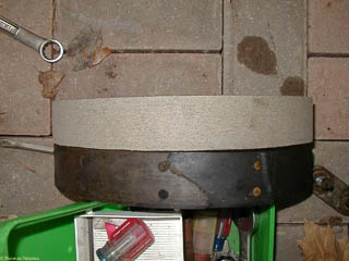
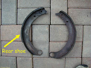
Since the truck was pulling right, we decided to look at the left wheel first. When we took the brake drum off though, half the lining of the front brake shoe basically fell out. You can see in this picture of the damaged shoe
next to a replacement (and no, we didn't just happen to have the replacement lying around -- the picture was taken later).
You can see the lining on the old shoe had been riveted while the replacement is bonded. I'm not sure what all the pros and cons are of rivets versus bonding: at one time, the adhesives used for bonding may have been suspect, but
I hope the bonded lining won't tear away the way this one seemed to.
I didn't get any detailed pictures of replacing the wheel cylinders or the brake shoes. In some ways it was simpler than "modern" drum brakes since there were no star adjusters, and the brake shoe hold downs are clips on the backing
plate. The one part that was tricky was getting the bolts and cams holding the lower part of the shoe in place.
Then it was time to bleed the front brakes, since the new wheel cylinders had gone on empty, of course. Starting on the right side (furthest from the master cylinder) and no problems. But then back to the left side, and the brakes
didn't bleed: the pedal was hard even with the bleeder valve open. So maybe the old wheel cylinder hadn't been sticking after all, but something else was stuck in the hydraulic line, preventing the fluid from getting to that
wheel cylinder and applying the brakes.
So, remove the flexible hose and try applying the brakes again. Just a dribble out the brake line. There's a junction block very near the driver side wheel, so there shouldn't be that much to clean out or replace. Applying a little
more brake pressure with the line open seemed to blast whatever it was out of the line, so reassemble everything; bleed both front brakes again (air might have got into the line past the junction block),
and this time every thing seemed good.
Parking Brake
One of the tricky things about replacing the 1935 mechanical brakes with 1939 hydraulic brakes is what to do about the parking brake. With mechanical brakes, the hand brake lever just pulls on the same mechanical linkage that pulls
the rod to each wheel brake assembly. When Ford went to hydraulic brakes in 1939, the parking brake lever was moved to under the dash instead of next to the transmission, probably to increase the amount of room in the front
seat since Ford also went to column shift at the same time.
The parking brakes are actuated by a cable that goes to each wheel and then along the rear wishbone to an equalizer yoke just behind the transmission. When we got the truck, the parking brake wasn't hooked up at all. Our mechanic
used some straight threaded rod to the equalizer yoke with a short bracket of 1/4" metal bolted to it and some wire cable attached to that metal piece connected to the bottom of the brake handle with u-shaped clamps. The metal
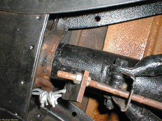
bracket allowed the cable to run straight back from the brake handle. You can see either end of this hand brake cable below.
The parking brake is adjusted by the nuts on the threaded rod, moving the bracket closer to the parking brake equalizer yoke (to the right in the photo).
You can see that force of applying the parking brake has caused the rod to bend over time, which also loosens the parking brake considerably. Other factors loosening the parking brake are stretching of the various cables and wear
in the brake shoes. We had already replaced the steel rod once, and the replacement bent even more easily than the original. So this time we got a brake cable with housing from Control Cables,
after measuring how long the cable and housing should be.
It was fairly easy to thread this through the frame and use the existing bracket on the rear wishbone. Securing the front end was a little more difficult, especially since the clevis on that end was larger than the end of the cable.We
solved this by cutting a U-shaped slot in one end of some 1/8" steel (done by first drilling a hole and then using a hack saw to cut the end open. This is used to hold the front of the cable housing. This bracket is bolted
to the frame while the cable itself goes through an existing, much larger hole in the frame. You can see this detail in the third picture above.
Rear Brakes
While this new cable tightened up the parking brakes some, they still didn't hold very well.Time to take a look at the rear brakes, and face up to possibly having to fix a broken brake adjuster. Newer rear brake drums tend to be
held on to the hub using the wheel and lug nuts, but on this truck, the drum was still pressed onto the hub, and the hub itself is held onto a tapered axle with a fairly tight fit (if it isn't tight, you'll ruin the spline,
the axle and the hub). Some shade tree methods for removing the hub from the axle include using a slide hammer, or just loosening the axle nut and driving in circles until the sideways force pulls the wheel off. Somehow, this
didn't sound very appealing, although neither did the thought of paying over $200 for a reproduction of the original K.R. Wilson hub puller tool.
The local NAPA came through and ordered OTC 7394 universal hub puller for me. I may have been able to pick this up mail-order over the web for a little less, but I'm not sure what the shipping charges would have been. Also,
J.C. Whitney has an inexpensive brake drum puller which might have worked, although some of the books I have cautioned against pulling the hub off the axle by the brake drum. J.C. Whitney also has a "professional
hub puller" for just under $50 which seems to be very similar to the OTC part: both come with three arms, but additional arms are available.
I don't have any pictures of this in use, but after taking the wheel off, you attach the puller arms to three of the lug nuts (not all on one side of the wheel!), tighten the screw against the axle with a little tension, then
strike the end of the thread with a hammer, or just the handle which can be used both as a wrench for the puller thread, or a hammer.
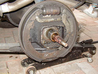
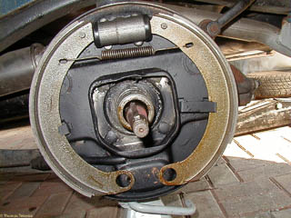
At least after paying all that money, the puller worked, even without any application of four letter words! That was good, because we needed a couple when we got the drum off and saw that another brake lining had disappeared! If
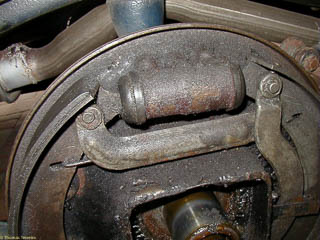
you look carefully at the photos, you can see one of the rivets on the rear shoe just dangling there. The lining itself resembled soggy cardboard! If you compare these pictures to the ones of the passenger side, you can see
that the driver's side looks like the wheel cylinder has been leaking which would explain the bad lining. I took and labeled the other picture here to make sure I put the linings back properly, after I got new shoes for the
rear as well as one new wheel cylinder (the passenger side looked fine, as you can see).
I've also highlighted the adjusting cams on the backing plate. It turns out that these were fine on the other side as well, but the driver's side rear brake wouldn't adjust properly because there was no lining on one shoe, not
because the adjusting cam had somehow broken.
I left the passenger side pretty much alone (except for replacing the brake shoes to match the new shoes on the driver's side). Here's the sequence of reassembling the driver's side:
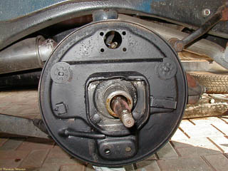
This is the backing plate for the left rear. The wheel cylinder was removed for replacement and painting.
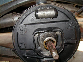
The wheel cylinder is installed next.
Next the brake shoes are installed along with the return spring. The trick to installing the spring and shoes is to put the spring on loosely with the shoes nearly crossed or crossed so the spring is loose. Then pull the shoes
outward to expand the spring, and fit the shoes under the hold down springs on the backing plate.
The anchor pin plate, anchor pins and brake shoe cams are installed through the round holes in the bottom of the brake shoes through the backing plate. This took the most time, for me, trying to get everything lined up. I think
the technique is to have the cam turned so the shoes will be as close together as possible.
Finally, the parking brake mechanism is installed. There's one bar going from the front shoe (on the left in this picture) to the parking brake lever. The parking brake cable goes into the end of the parking brake lever. There's
lots of slack in the cable in this picture. The cable was pretty tight when I got both sides installed.
I don't have any detailed pictures of adjusting the brake shoes, but there are two steps involved, and to get the parking brake to work well, it was necessary to adjust the anchor pins and cams to move the lower part of the shoes
outward. Plus I'm sure that's generally a good idea so you use all of the brake shoe for stopping.
Fuel Pump and Carburetors
We've often had trouble starting the truck after it had been sitting for a week or more, although this problem seemed to go away for a good long time after we got the short pieces of rubber hose between the main fuel line and fuel
pump tight. At some point I must have removed the cover on the fuel pump to see if fuel was getting there, and must not have tightened it properly: the result was the sediment screen in the fuel pump got rusty, and the pump
stopped working because of the air leak. Things went from bad to worse when I checked again and while trying to clean the screen, broke the cork gasket. We have the correct style fuel pump for 1935 (no glass bowl), and the
gasket wasn't available separately. Besides, with the rust, we figured we'd better replace the entire pump.
Replacing the fuel pump was easy enough, but we continued to have trouble with running poorly, and especially with the carburetors flooding and leaking. This seemed to be from the valve needle and seat by the float leaking. This
was annoying because sometimes it would leak badly, and other times it would be okay. After pulling the needle and seat one time and seeing a fairly big piece of rust on the needle, we realized we ought to clean the carburetors
more thoroughly, since when they weren't flooding, the engine was still stumbling.
As is my usual practice, I ended up cleaning and rebuilding the carburetors twice: once just taking them mostly apart, spraying the passages with carb cleaner, and putting it back with all the original parts. After the confidence
boost of having the truck still run afterwards, but being concerned by the condition of some of the internal parts (particularly the power valves), I decided to get more replacement parts and do a proper rebuild.
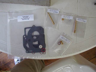
We had bought the carburetors professionally rebuilt, but some parts were clearly used. I think since that time (about two years ago), more new replacement parts are available. In particular, Charlie Price at Vintage Speed is
now selling new emulsion tubes, new power valves, and new accelerator pump check valves. He also has a tool for removing the emulsion tubes. I hadn't touched these during the first rebuild after reading the dire warnings about what
could happen if you don't have the right tools. In retrospect, I probably should have got a master rebuild kit with some different size main jets and replaced the idle screws, just in case. But like any good Red Sox fan, I know I can just
wait 'til next year...
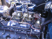
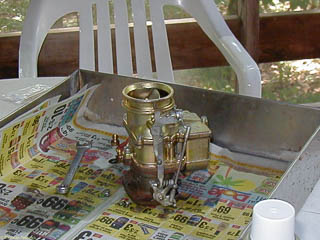
I left the air cleaner on when I took the carburetors off the truck. I removed it, and removed the plugs over the main jets and accelerator pump, draining the gasoline into a can (not shown). You can see the plugs just behind the carburetor.
I had previously got Flathead Jack's plugs with hex heads instead of the standard slotted screws (there's nothing more dangerous than a software engineer with a screwdriver, and I do less damage with a wrench!). This is still not a complete
rebuild, since I didn't touch either the choke plate or throttle plate, and just moved the throttle linkage out of the way so I could take the top off the carburetor.
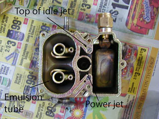
I removed the top section of the carburetor, leaving the fuel pump in place as well as the choke plate. Looking down the top of the bowl section, you can see the ends of the emulsion tubes inside the venturis. The screw head in the middle
is the top of the idle jet. I didn't remove the float since I thought my flooding problems were due to dirt in the needle and seat, not a misadjusted float. I did remove the needle and seat later to make sure they were clean. Oh, and these
pictures will do double duty: economists in the future may be interested to know what Coca Cola cost in the summer of 2001!
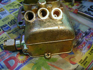
I turned the bowl upside down and used a jet wrench to remove the main jets. You can now see the end of the emulsion tubes.
The tools for removing the emulsion tube are a 10-32 tap and a long 10-32 screw with a nut and washer: first tap the end of the emulsion tube, and then use the screw as a puller, with the washer and nut where the jet plug would be: thread
the screw into the emulsion tube, then turn the nut to force the screw and emulsion tube to pull out of the press fit.
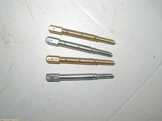
The old and new emulsion tubes are shown here. For some reason, the old tubes were silver colored, while the new ones were unplated brass. A big surprise was that on one carburetor, one of the emulsion tubes only had two holes on the top rather
than four. I'd been worried that the holes might have been collapsed, which is what various books warn about, but don't know why some holes might never have been drilled out at all. I also think that the emulsion tubes may have already
been tapped since the 10-32 tap seemed to start very easily. I would recommend that anyone removing their emulsion tubes first see if a 10-32 (or maybe 10-24) screw will already thread into the end.
To replace the emulsion tube, just set it back into the carburetor, and use the main jet to push it in and hold it in place. One of the emulsion tubes on one of my carburetors just slipped all the way in, but the others did have to be pushed
in. In the second picture above, you can see the emulsion tube in the top venturi. Off to the left of the picture is the other main jet, and the ends of the idle jets, waiting to be installed. You can see where they have been removed from
the top of the carburetor bowl, and also see that the needle valve and seat have been removed for cleaning, but the float is still in place.
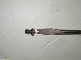
The last piece I replaced was the check valve beneath the accelerator pump. This is removed or installed with a plain straight blade screwdriver and goes behind the middle plug on the bottom of the bowl of the Stromberg 97. My only clue that
there might have been anything wrong with either of these had been the presence of what looked like epoxy or thread sealer on the old check valves when I took them out.
I reassembled with mostly new gaskets (I had meant to order the gasket kit with the thick gaskets, but must have messed up, so I re-used some of the previous gaskets which were still in good shape. I did replace the gaskets between the
base of the carburetor and the intake manifold.
I also had removed the idle adjustment screws from the base of the carburetor sprayed the idle passages with carb cleaner, but didn't attempt to remove the plugs for a more thorough cleaning.
Anyway, if the proof of the pudding is in the eating, I haven't had any more problems with carburetor flooding, or with stumbling. I also was able to adjust the idle speed much lower than I had previously, but maybe that was just that
I was willing to set the idle speed much lower.
Water Pumps and Block Off Plate
Brief summary: one of the block off plate used with older heads on an 1937 block was leaking. It had to be removed, the sealing surface cleaned, and replaced using RTV as a gasket.
There was still a coolant leak, most noticable as a fine spray coming off the fan belt. This turned out to be the left hand water pump. I removed both water pumps, determined the right hand one was fine. Broke the pulley on the left hand water pump trying to remove it with a puller (wrong choice of tools: ended up using a drift punch and a hammer). Rebuilt the spare water pump that was in the back of the truck and also ordered two new reproduction water pumps which I'm keeping as "insurance". Pictures of the rebuild of the other water pump after getting a replacement pulley.
Horn
Not enough clearance for the modern horns under the fenders, and the right hand horn was shorting against the frame with the wheels turned hard to the left. This motivated me to try to fix the left hand horn, but I couldn't get it adjusted right. I'm assuming that this is because it was intended for six volts, and with twelve volts the spring rates don't match the voltage. I bought a new horn which works, but needs a relay to work (the horn seems to be internally grounded), and doesn't sound as nice as the other horn. Oh well.
Distributor and Ignition Coil
Never oiling the front bearing in the distributor causes it to squeal. Imagine that! Punted and bought a rebuilt distributor rather than trying to just replace the bearing.
Decided at the same time to use a stock style dome shaped coil on top of the distributor. Picked up several of these at swap meets (everything I've read says you should always have a spare!) Trying to find a ballast resistor that won't burn the coil up and also won't burn itself up. Currently using two 1.8 ohm coils and seeing what happens.
What's Next
While nothing major is planned. Follow the link to see other planned or unplanned activity we've done.

