Looking at Spare Parts
After we had the truck in our garage, we started taking a more serious look at all the stuff in the bed of the truck. We also spent some time trying to find out whether the truck was currently set up for 6 Volts or 12 Volts, what
would be involved in converting, and what good were the spare parts.
Gauges
We want to basically use the truck as a truck so we're not really concerned with keeping things original. At the same time, Gillian doesn't want to carve up the dash board if it can be at all avoided. The most serious problem here
is gauges: the dash board has three circular holes: one large opening for the speedometer, and two smaller ones for everything else. The original gauges seemed to be grouped in pairs: temperature and ammeter in one small gauge
and oil pressure and fuel level in the other.
Unfortunately, the gauges we have don't look like they would work, or at least wouldn't be practical to use these days. In the picture above you can see one mechanical temperature gauge, pretty similar to what you might find today
except the read-out is a liquid bulb thermometer rather than a dial. The readout is in the upper left corner of the picture shown above and the "cable" snakes around the picture to the sending unit on the lower left. At the
lower right of the picture is another readout for water temperature except the sending unit has been cut off.
The only other two gauges which look as though they might work are a fuel gauge and ammeter shown in the center. I don't know what they originally came out of, but I don't think they came from a '35 pickup truck since there aren't
enough mounting spaces for these one-of gauges. The gauge faces in the picture to the right are a mixture of these single gauge and two-gauge pods.
While mechanical gauges for water temperature and oil pressure work on the same principle today as they did fifty years ago, electric gauges work very differently. According to various Ford technical service bulletins from the
30's, many of the gauge sending units and displays worked by heating a bimetallic strip to open and close a circuit. This in turn would heat a bimetallic strip in the gauge display. Today, with inexpensive semiconductors, electric
gauges typically sense a resistance from some sending unit and convert this to an appropriate current for an appropriately calibrated ammeter in the gauge: if you look for information on a fuel tank sending unit for a modern
fuel gauge, the relevant parameters are the sender resistance for a full tank versus and empty tank. For the 1930's electric gauges, the operating voltage is what's important, and the gauge is going to use some power.
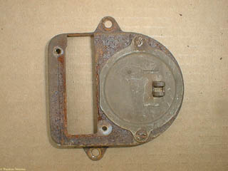
As an extreme example, the picture above shows the back of either a combination ammeter/water temperature gauge or oil pressure/fuel level gauge. The blank space is for the thermometer readout or fuel level; the ammeter or oil pressure gauge
is on the right. While I can't be sure, it doesn't look like you hook wires up to this gauge. Instead, it looks like you might put a heating coil through the little hoops, and the gauge looks like a specially calibrated thermometer! Note from the future: more likely, this is an ammeter. The charging wire from the generator is fed through the loop and operates the gauge by electromagnetic induction.
The speedometer, thankfully, looks almost normal. The color scheme looks somewhat muted, but Autometer has some gauges in a very similar color scheme that we will probably use in our truck somehow. I don't believe that our truck has only traveled
42 thousand miles, and the dash has very similar speedometer but with no miles showing on the odometer. It's interesting to note that even back then cars had trip odometers (you have to reach around the back to reset it though). The one shown
here only reads to 100 miles. The one in our dash reads to 1000 miles.
Just to keep everything interesting, not only do we only have two holes to some how squeeze in four gauges, these holes aren't a standard size (at least not today's standard size). The small holes are 2 3/8", just a little too large for a 2" gauge,
and too small for a 2 5/8" gauge. The speedometer is also a random size, but if either of the ones we have work, we'll just keep it.
Sending Units
Although we haven't figured out how to get enough new gauges in the dash, we've pretty much decided to upgrade to a 12 volt positive ground and modern gauges. And while the funky electric mid-30's gauges only work with funky mid-30's sending
units, amps are still amps, volts are still volts, and other sending units for temperature or oil pressure still have to connect mechanically to the engine block where plumbing standards, not car standards, rule.
There's just a plug now where the coolant temperature sending unit goes, but it looks like a 5/8" standard pipe thread plug. Today's gauges come with adapters for 3/8" or 1/2", but getting an adapter for 5/8" will be easy, even if it's an
adapter on an adapter. There is an electric oil pressure sending unit in place now, but that will get junked, if needed, and replaced by something modern.
The electrical system is still 6 volt positive ground with a generator, but the generator is missing the "generator cutout" (otherwise known as a voltage regulator). Since I don't have any original working gauges or radio to worry about, I'll
convert it to 12 volt negative ground by putting in a Chevy one-wire alternator (which means using a voltmeter to see how the battery's doing instead of an ammeter to see how the charging system is doing).
Everything I've read says I can keep the 6-volt starter motor, and after nearly three years, this seems to be true. People have said to be careful about cranking the starter motor for a very long time, but I've had to crank for a minute or
more to get fuel back into the carburetors and haven't had any problems. Some people caution that the extra juice of 12 volts is harder on the bendix spring, but I haven't encountered that. Other people say that the coils are heavy
enough to stand a lot more current (and therefore voltage). In any case, I'm keeping the 6-volt starter until it burns out.
The only roadblock now on sending units is what to do about the fuel gauge. The factory '35 fuel gauge was actually mechanical: there was some sort of "air line" from the fuel tank to the dash board. I can't remember where I saw it, but apparently
you can still get red fluid to put in the indicator gauges, but this is not for me.
What is a problem is what to do for the fuel tank sending unit. Remember that stuff about bimetallic strips and stuff in old sending units? Well, that's what Ford changed to in 1936 (or maybe even some 1935 models). As you
can see from the picture, I've got plenty of sending units to choose from. Some of them might even work, if I had a matching gauge. Unfortunately, I don't. Neither of the restoration catalogs I have at the moment (
Sacramento Vintage Cars and Dennis Carpenter Reproductions) seems to have modern sending units. I'll need to call to make sure, but if the catalog says "6 Volts", I'm skeptical.
Sure, if the sending unit is just a variable resistor, the same sending unit could be made to work with a 6 volt or 12 volt gauge. But if the sending unit works by heating a coil close to a moving diagphram, I don't think today's gauges
are going to sink enough current to the sending unit to ever move the needle about 'E' (or below 'F'', depending on which way the gauge goes).Again, I'd love to hear by e-mail if I'm
wrong.
So then I tried tactic two: look for a modern fuel gauge. Well, the gas tank on my truck has 6 screws holding the sending unit: modern cars seem to have 5. Autometer sells a generic sending unit for it's fuel gauges, but they use 5 mounting
screws in a 2.12" diameter circle. The sending units I have are more like 2 3/4". I'm running out of ideas, but my wife thinks that maybe a 1950's F-100 sending unit will fit the gas tank and work with modern gauges.
Other Stuff
We spent much of the afternoon sorting through the other stuff in the bed of the pickup truck. Here's what the bed of the truck looked like when we were through: Although it's common to see trucks at shows with beautiful hardwood beds, in
1935 they had a steel floor on top of a wooden subfloor. You can get reproduction beds, as well as the sides of the box and the tailgate. The floor on this bed looks fairly authentic, or at least well covered by small dents as if it's
been used. That rectangular hole on the left is supposed to be there: it provides access to the previously mentioned gas-tank sending unit.
One of the other quaint pieces of automobile nostalgia is vacuum operated windshield wipers. It's been nearly 30 years since electric motors became cheap enough to simply throw away (Polaroid's SX-70 cameras had an electric motor in each film
pack that was supposed to be thrown away after the film was used up. When I was a freshman at MIT, several professors were thinking up student projects to use these "free" motors). But fifty years ago electric motors were still serious
stuff. Our truck came with one electric motor: the starter. And it still has a mechanical backup for that (anyone who has a crank that will fit, please let me know). Note from the future: we eventually got a reproduction engine crank, but have never tried to start the engine with it.
The windshield wiper operated off engine vacuum. When new, these work fine. But after a while, the seals on the paddle start to leak and the wipers slow down. And since it works off engine manifold vacuum, your wipers tended to slow down when
you accelerated: just the wrong time to obscure your vision. Curiously, vacuum wipers were around even after Polaroid was throwing small electric motors away: we had a '71 AMC Gremlin (bought used, just after graduating from college) that
had vacuum operated windshield wipers. But many cars built in the 60's had already switched to electric wiper motors.
And yes, that's "wiper", not "wipers": a wiper for the passenger side was an option. Our truck has mounting holes for both windshield wipers, and instead of mounting under the hood, the wiper motor mounts in the roof and the wiper sweeps down.
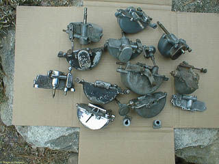
The optional wiper uses its own vacuum motor. You might think that we've got plenty of wiper motors to choose from, but almost all of them seem to be frozen internally. Some seem to be missing parts of the wiper shaft, but most some complete:
just stuck. We were already advised to either stay out of the rain altogether and/or use Rain-X to keep the windshield clean. We'll take the second suggestion and also put in electric wiper motors.
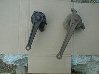
This isn't to say that there weren't some advantages to vacuum wiper motors. Adding variable speed just requires a way to limit the air flow through the vacuum motor. The "deluxe" wiper motor above has a control shaft for the speed on the
far right. The rod just to the left slides back and forth and functions as the ON/OFF switch (though often by sliding this partway you should be able to control the speed as well). The wiper arm attaches to the shaft coming out the top
of the wiper motor. You can just see the vacuum port on the other side of the right most control knob. The shaft sticks through the roof just above the windshield and the control arms stick through holes in a cover plate where the sun
visors would be (remember, this is a "no frills" truck) and you control them from there. Vacuum lines from the engine manifold get routed through the firewall and inside the cab.
Door and window handles
Because we got the truck not quite finished, we got a lot of miscellaneous parts that might be needed at some point. We were told that "everything that looked Ford-related was put in the back of the truck" and we have to agree. Our truck has
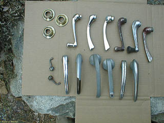
two doors, but we have enough door and window handles to equip a fleet. Most of that brown stuff isn't rust: at that time, the deluxe interiors were painted brown instead of chromed. The brown is what's left of the paint which was fairly
thick and looks almost like a plastic plating or coating. I think the dull finished handles just lost all of their paint, although they could also have been just unchromed, unpainted castings.
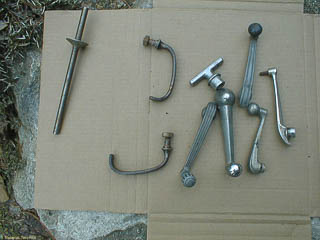
There are a variety of other types of handles as shown in this other picture. We know what some of them are. For example, the C-shaped handles are latches for the hood on some different year Ford. The short T-shaped handle is used to open
the windshield which is hinged at the top and pushes out at the bottom to provide ventilation. We don't know what the spikey thing is: maybe a stake to exorcise old car demons?
Horns
The truck came with these beautiful old horns.While the black one looks more truck-like, the chromed one actually looks older when you look inside. I suspect that the original horn is long gone and these were found at swap meets somewhere.
I had to bring the horns back inside to take a picture of the insides and put the chromed one onthe right. The mechanism is basically a buzzer acoustically amplified by the saxophone-like passage at the bottom. The innards of the chromed horns looks
much more rusted and primitive than the black horn. Neither horn seemed to work so we plan to just use the bracket from the chrome horn to mount a replacement horn that looks like one of these. Other options include putting this horn on just for
show and putting a cheap horn inside the engine compartment, or trying to put new horn guts in one of these horns.
Of course after looking at these pictures we thought, "Hey, wait a minute! Why not try to fix the horn? It's just a buzzer, right?!"
Well, we went to work on the old horn, took it apart and cleaned some gunk and rust out. And then went about discovering how complex a buzzer can be. Actually, it issimple: just an electromagnet and a spring switch attached to iron.
When the current is on, the magnet pulls the switch open which then turns the magnet off. The spring pulls the switch closed again. The complicated part is getting the spring tension and travel just right so the magnet will open the switch (and
not just short the battery) and makes a noise with the right frequency and volume.
We did find a technical service bulletin for the horn showing how it was supposed to be assembled and after even more fussing around and adjustment we were able to get a few very pitiful squeaks out of it, mostly poor contacts.With even more fussing
we got a sound like a quiet door buzzer before the vibration misadjusted itself. Gillian is still working on cleaning the contacts and trying to tighten the adjusting bolts to keep working.
Shock Absorbers
While the truck drives, none of the shock absorbers are on the truck. And like just about everything not installed, the back of the trunk is filled with used (and probably non-working) candidates. There are a few of these original style shock
absorbers which work on torsional rather than linear resistance. I haven't seriously tried all of these, but they seem mostly frozen up. You can get remanufactured versions of these for $120 each. I think we'll pass, but you never know. The
original style are adjustable and every spring and fall you're supposed to top off the shock absorber fluid. The biggest problem would be finding the right control arms since I haven't found these in a catalog yet, and we
don't have four control arms total, let alone a set that may work on this truck.
What we do have is lots of adaptor brackets which bolt onto the frame in place of the torsional shock absorber and provide an attachment point for the top of a modern style shock absorber. I didn't take any pictures of these or of any of the twenty
or so cartridge style shocks which are probably worn out and will have to be thrown out.
What's next?
Well, that concluded our tour of the parts in the back of the truck. There are also other useful things like new door window glass, the door window regulator that has been installed yet, some of the weather stripping and original brackets for
the window (some will get used, some we'll have to replace), a few bits and pieces of headlamp reflectors, some brand new headlight reflectors with halogen bulbs, tail lamp assemblies and what nots. Follow the arrow below to see how we got
this stuff installed.

