
Installing Parts
After a week or so of waiting, various parts started to arrive via mail-order supplemented by smaller parts obtained from local hardware or autoparts stores: things like screws, wiring, crimp-on electrical connectors and so forth.
Most weekends in March and early April (and some of the evenings) were spent trying to get things installed. As of today (Easter Sunday), we're almost ready to get the truck registered: the only safety related
item missing is the parking brake cable. We also need to get shock absorbers, but I don't know if they're required for the state inspection. There's still no interior, we're waiting for some wait to mount the last two gauges,
and there's still a surprising number of small things left to do.
Chrome: The Bright Stuff or the Dark Side?
Chrome plating or other shiny features generally don't make a car go faster. By itself, they don't make the car more reliable either except to the extent that they encourage you to keep that part of the car or engine clean and
free of rust. I don't remember exactly when things changed from lots of chrome to "black out" treatment. Exterior chrome can cause glare on sunny days, but it's not a problem under the hood.
In any case, we had to do something about the generator to switch from 6V to 12V electricals. There already was a 12V battery and ignition coil, but it was set up for positive ground. After reading about the pros and cons of generators
versus alternators and recognizing that we had a generator of unknown type, no voltage regulator for it, and the parts catalogs we had at the time had replacement 6V regulators (or "generator cutouts"), but nothing for 12V
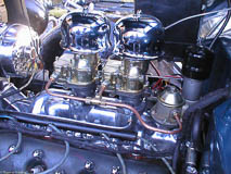
made it easy to decide to go with a one-wire Chevy alternator with internal voltage regulator. We could get the new support bracket plain or polished. We went for the polished one as shown here as well as a chrome plated alternator.
The pully at the lower left is for the 5/8" wide belt instead of a newer 1/2" belt. We got all this from Hot Rod and Custom Supply (their printed catalog has a lot more flathead stuff than you'd guess from looking
at their web site). They also had helpful technical people available. Since our engine is a '37 block, finding a bracket that works (or any parts, for that matter) is more difficult than for '39 or later engines. Note from the future, Hot Rod and Custom Supply no longer has a web presence, but may still be in business.


Click on any picture to see a larger image
If you look at the original generator, you'll notice that the cooling fan was attached to the generator pulley. We asked the folks at Hot Rod and Custom Supply about that, and while they don't have it in their catalog, they know of someone who makes
pulleys that will let you attach a fan. Unfortunately, these seem to be made out of unobtanium (seemingly a previously plentiful material now in short supply), but if we placed an order for this pulley, they would now have four customers waiting
for the pulley. We ordered a plain pulley and put in the electric cooling fan you can see in the third picture.
Gauges
Although we liked the look of Autometer's "Golden Oldies" gauges, the suggested list price for these gauges was higher than the catalog price for Stewart-Warner gauges in the Speedway catalog. Note from the future: I think we were looking at what Autometer now calls "light beige". Due
a "brain fart", I forgot to look in Summit Racing which carries Autometer and has the Autometer gauges for a little less money, but neither gauges seemed to be in keeping with the original
speedometer we have. The Stewart-Warner gauges have red needles instead of black and slightly different markings.
The 2" gauges slip right through the holes in the dash, but we took apart some of the old gauges and used the trim plates to hold the new gauges and attached the old trim plates to the dash. Here's a picture of the fuel gauge ready to be installed.
If you look at the large picture, you can see that Stewart Warner outsources the gauge faces at least. We have the fuel gauge to the left of the speedometer and the water temperature gauge to the right. Unfortunately, that's all the holes
in the standard dash and there's no convenient place to put more holes with the original speedometer. Several people seem to make dash inserts that use a modern, smaller speedometer (3 5/8" instead of nearly 5") and have room for all the gauges.
For now, we have the additional gauges mounted on inexpensive brackets below the dash. In the third photo you can see the add-on turn signal switch. It looks like something from the 50's and more in keeping with the rest of the cab than putting
in a modern GM steering column.


We did get a small scare with the speedometer: we figured that since the one in the dash reads 0 miles, it must be rebuilt and working. However, when we connected the speedometer cable and tried to turn it, first by hand and then slowly with a
portable electric drill: no go. Momentary panic and looking for various solutions. The other speedometer in the back of the truck was also stuck. We didn't actually call any of the places speciallizing in repairing old gauges, or putting modern
gauge works into new cases. We did bring the speedometer cables to a local speed shop, and they didn't have a clue as to where you'd get a speedometer head that worked with that cable or speedometer gears that looked like the other end of
the cable. So, we went home, took the speedometer out of the dash and tried again. It turned out that speedometer was okay, but was initially stuck when the cable was fastened too tightly. After adjusting an O-ring to the
right position, everything seemed to work (and we put 0.1 miles on the odometer with the electric drill testing it).
The speedometer cable actually attaches to a gear unit on the drive shaft, not the transmission. The speedometer gear on ours has the number "19" cast in it which caused some other momentary concern: we had found some tables showing rear axle
gear ratios and corresponding speedometer gear ratios, and it was only the 3/4 ton or larger trucks which used the 19-tooth speedometer drive gears, and they had something like 5.6:1 rear axle ratios. We had thought the standard 4.11:1 "stump
puller" gears would be bad enough at any sort of highway speeds, but 5.6:1?!
To find out what we really had, we jacked up one wheel and turned it to see how many times the drive shaft turned. Since the truck has a "closed" drive train we had to peek at the speedometer gear since the the drive shaft itself is covered by
a "torque tube". It took 1 1/8 turns of the wheel to get the drive shaft to turn two revolutions. If both wheels had been free to turn, it would take four revolutions to 1 1/8 turns of the wheel or just about 3.55:1. The Ford service bulletins
mention an optional 3.54:1 rear gear that is supposed to have an 18 tooth speedometer gear, so at the moment, our speed will read about 5% low, but we should be able to cruise without any trouble.
Gauge Sending Units
With all new gauges we got all new sending units. None of these ended up fitting without some sort of adaptor. The original gas tank sending unit uses a much larger diameter hole in the tank, but Stewart Warner sells an adapter kit: basically
a donut-shaped steel plate with holes for mounting the sending unit that we J-B welded to the tank. Of course, just to keep things interesting we hadn't noticed that the 5 holes were quite symmetrical after all and had to spend some time fussing
with the sending unit so the float arm wouldn't hit the side of the tank.
Everything I've read says I can keep the 6-volt starter motor, and after nearly three years, this seems to be true. People have said to be careful about cranking the starter motor for a very long time, but I've had to crank for a minute or more
to get fuel back into the carburetors and haven't had any problems. Some people caution that the extra juice of 12 volts is harder on the bendix spring, but I haven't encountered that. Other people say that the coils are heavy enough
to stand a lot more current (and therefore voltage). In any case, I'm keeping the 6-volt starter until it burns out.
Just to see how gauges would fit into the dash at all and whether new sending units would work, we had gone to one of the local discount autoparts stores and bought the cheapest mechanical temperature gauge we could find. That sending unit fit
perfectly without any adapter so we thought we were all set. WRONG! The sending unit for the electric temperature gauge didn't quite fit, but neither of the adapters that came with the mechanical unit fit either. A trip to the local Home Depot
educated us on the difference between a 1/4 NPT pipe fitting and a 1/4 NPT flarefitting.
That left just the oil pressure sending unit. The big problem there was how to get the old sending unit out. It didn't look like it should cause any trouble, but it was almost impossible to get a wrench on. Once you did, you could move the wrench
all of about 5 degrees, but the sending unit had a 4-sided "nut" to tighten it into the block. It didn't seem likely that you had to pull the engine to remove the oil pressure gauge, but what other way was there?


The main floor of the cab is wood. You have to remove this to get access to the battery, the brake master cylinder or parts of the transmission. There's another removable metal panel across the lower front of the cab between the firewall and this
wooden floor. If you remove this metal panel you can get at the oil pressure gauge fairly easily (highlighted by the yellow arrow in the right hand picture). Yes, it's a kludge, but much easier than pulling the engine! Of
course the oil pressure sender also needed an adapter (3/8" to 1/2" NPT, if I remember correctly).
Choke/Throttle Rod Connectors
Flathead engines have manual chokes and also a dash panel throttle connection that lets you set a fast idle while the engine is warming up. You can see the choke and throttle rods on either side of the carburetor extending back towards and into
the cab. The dash panel has two shorter rods with knobs labeled "throttle" and "choke". With a simple, direct mechanical connection, what could go wrong? Simple: maybe; direct? not that you'd notice! There's a simple sleeve that both rods
fit into. When we got the truck, pulling the choke knob set the choke on the carburetor and then pulled the knob right out of the dash. This sleeve which I guess is supposed to be a friction fit was cracked and mangled and didn't hold the
choke rod. Ditto for the throttle rod. Armed with plenty of catalogs of reproduction parts, we ordered another pair of sleeves. These new sleeves seemed to be just like the previous ones and the rods just slid out of the sleeves.

Our first attempt to remedy this was to install set screws in the sleeves: you can just barely see one set screw by the yellow arrow in the picture. The original circuit breaker and ignition resistor is at the green arrow and the red arrow
points to the cowl vent ratchet.
This wasn't too successful, probably because we didn't have suitable taps for such shallow holes. We tried to squeeze the sleeves to make them tighter, but that didn't get us anywhere. We ended up using RTV to hold one pair of rods together
before finding some nice aluminum spacers already threaded for 10/32 threads. The right solution (at least as far as we're concerned) is to use a 10/32 die to thread the ends of the rods and use a threaded spacer instead
of a sleeve. I wonder what they did back in the 30's?
Front Turn Signals/Parking Lamps
I'm not sure when electric turn signal lamps were introduced, but I think it was some time in the 50's. Certainly they were not available on Ford cars and trucks in the mid 30's. They did have brake lights separate from tail lights at that time
and parking lights, but the parking lamp is an additional low power bulb high in the headlamp reflector. I did locate one source of turn signal switches that can use one filament for both a parking lamp and turn signal at Ron Francis's Wire Works,
but we weren't interested in putting in the push button turn switches. Also, the headlights already had been changed to use a single halogen bulb and we would have had to punch an extra hole in the reflector to fit a parking lamp into the
headlight bucket.


Instead, we got cowl lamps for a '32 Ford that had already been set up for dual filament bulbs. Ordinarily these would be mounted just in front of the doors on either side of the cab. We got some steel bar, drilled mounting holes and bent it to
attach to the front bumper. Here are pictures of the lamps on the brackets as well as the lamps mounted on the front bumper.
Wiring for Turn Signals
Several companies sell retrofit turn signal switches for old cars: J.C. Whitney's has one, Ron Francis's Wire Works has one: most of the mail order catalogs for pre-1950 cars have them. They all look a little big and clunky and vary in price from
around $30 to $70 or more. We ended up getting one from the local Parts America (used to be Western Auto, I think, and now owned by Sears). It came with instructions in English and Spanish. I should ask my daughter about the Spanish, but my
guess is that the English instructions are a translation. You can just see the turn signal switch to the left of the steering wheel in one of the pictures above. It's supposed to clamp to the steering column
using a hose-clamp like band, but this just slipped off, perhaps because the steering column on this truck is pretty small. We removed the half a clamp they supplied with a real stainless steel hose clamp.
The rest of the wiring was more work. Relatively speaking the wiring in this truck is very simple: there's no radio, no heater, no courtesy light, no engine computer. Originally there were four separate wiring harnesses:
- Main wiring harness from inside the cab to the ignition, oil pressure gauge, light switch and the battery (actually, the battery side of the starter switch)
- Front lamp and horn harness to the headlights/parking lamps and horns
- Rear wiring harness for the brake lights and tail lamps
- Tail lamp crossover harness
In order for turn signals to work you need to change the brake light wires to allow each bulb to be turned on separately and add wires for the front turn signals. The wiring for the brake light originally went from the battery through the brake
light switch and then back to the brake lights. The wires to and from the switch need to be brought into the cab to the turn signal switch.
Unfortunately, we didn't take pictures of what we did to each harness so I'll just describe it, starting at the rear of the truck moving forward
Tail map crossover harness
This is a very simple harness that takes the wire for the tail lamps (black) and the brake lamps (green) and brings it to the driver's side and passenger side lamp assemblies. The black and green wires are spliced at a bullet connector which attaches
to the rear wiring harness. We left the black wire completely alone and just cut one of the green wires right at the splice by the connector and put on another bullet connector. This let us turn on the brake lamps independently. The turn signal
switch uses the brake switch and turn signal lever to turn on either one brake lamp or both brake lamps as needed.
Rear wiring harness
This harness originally had a black wire going the full length for the tail lamps, a yellow wire for the fuel gauge and a green wire that came out of the harness about three feet from the front to connect to the brake light switch. I'm guessing
that since it was set up for an electric fuel gauge already it must have been for a '36 or later truck since the '35 originally had a pneumatic fuel gauge.
We spliced together the two green wires for the brake switch and used this to connect to one of the rear brake/turn signals. We added another wire to go the full length of this harness for the other rear brake/turn signal. We added two new wires
to go to the brake lamp switch. The reproduction harness we had was nicely wrapped in a braided fabric cover. We thought about just using tie-wraps to hold the extra wires in place, but even though these are one of the "10 best tools of all time",
we decided not to use them, at least not for this (we did use tie wraps to hold the wiring harness to the frame when we couldn't get the wiring clips to fit over the wire harness). We used fabric friction tape to wrap the extra wires to the
harness.
Front lamp and horn harness
This harness actually includes the guts of the light switch which mounts to the lower end of the steering column instead of being inside the cab. This harness takes a power feed from the lighting circuit breaker and provides a splice back to the
brake lights through the brake switch. We just taped off the connector going back to the brake lights since we changed all the wires for them. This harness also has a black wire to connect to the black wire on the rear wiring harness (for
the tail lamps) and feeds forward for the parking lamp, low beam and high beam for the left and right head lamps. The front harness also has two wires for each horn. Power for the horn comes straight from the starter switch and the horn switch
is wired in the ground wire return from each horn. The wire for the horn switch actually goes inside the steering column, but that's another story.
We had to add two extra wires for this harness: one for the left front turn signal and one for the right front turn signal. We again used friction tape to attach these wires to the harness.
Main wiring harness
We actually left the main wiring harness alone outside the cab, but did cut apart a couple of spliced wires inside the cab: the charging wire for the generator was spliced with the wire feeding power to the ignition switch; the wire coming from
the other side of the ignition switch was spliced to feed the ignition resistor directly. Cutting these splices apart let us connect things to separately fused circuits using a modern wiring block.
We had to get a total of nine additional wires out of the cab and decided to make a whole new harness for these instead of adding them to the existing harness. These new wires were:
- Left front turn signal
- Right front turn signal
- Left rear turn signal
- Right rear turn signal
- To brake light switch
- From brake light switch
- Water temperature sending unit
- Power feed for electric cooling fan
- Power feed for horns
Again, we used friction tape to make this harness.
Other wiring changes

The only fuse or circuit breaker in the original wiring is a single fuse for all the lighting circuits. This was later changed to a circuit breaker and that was what was in our truck when we got it. You can see this at the green arrow in the
picture above showing part of what's underneath the dash. We replaced this with a modern 12-circuit fuse panel made by Painless Wiring. I didn't take any pictures of this before installing it, but it tucked away nicely up behind the dash.
About the only change we made was to replace the horn relay with a jumper wire since the original horn wiring isn't set up for a relay.
You can also see a couple sections of the original wiring harness (the black cloth braid with bits of red) and a modern split-plastic loom that is part of a gauge wiring harness also made by Painless Wiring we bought.
Cowl Vent Ratchet and Spring
Although there's no heater and no air conditioner, the truck is set up to keep you cool. There's a nice big vent on the cowl just in front of the windshield that opens up and directs air at your feet when the truck is moving. If this isn't enough,
you can open the whole windshield which is hinged at the top.
Our truck came with most of the parts we needed: it had the cowl vent handle and hinge, but was missing a spring and a "ratchet" to hold the vent open. '35 and '36 pickup trucks are a bit of a black hole in the reproduction parts catalogs, even
though many of these are the same as '34 car parts. I suspect that the Ford chassis parts books covering those years would be very useful to make your own cross reference of what parts to use.
Anyway, finding the spring was easy and when we did get the ratchet from C & G Early Ford parts it was labeled something like "32-34 Ford car and 35-36 pickup". It was hard to see how to get it in place. We could fit the ratchet in without
the spring, but couldn't figure how to stretch the spring once the ratchet was in place. We tried filing down one end of the ratchet and enlarging a hole at the other end that fit over a hinge pin to try to get more room to maneuver. What
finally worked was attaching the spring end, using a screw driver wedged against the cowl vent handle to provide a pivot point and that gave just enough clearance to slip the other end of the ratchet over the hinge pin at the top.
You can see the cowl vent ratchet and handle by the red arrow in one of the pictures above.
Windshield Wipers
We had a plethora of vacuum operated windshield wiper motors, very few of which seemed be repairable, much less working. Besides, we've had cars with vacuum operated wipers, and even if we don't expect to have to drive in the
rain much, some things were just meant to be modernized. And there are lots of different electric wiper motors to choose from. We know 'cause we chose the wrong ones. At least not the best fitting ones.
What we think may be the best are also expensive. There's a place by Seattle (of course) that makes "Mighty Wiper" motors. With the wisdom of hindsight, these are probably the ones we should
have bought since they seem to the physically the smallest, and the wiper motors have to mount inside the cab above the windshield. We bought that are just a bit to deep to fit completely behind the access plates. We put
some weatherstripping to take up the 3/8", but since the wiper case touches the metal cab and uses it as a sounding board, the wipers are loud. Of course, with the engine running, the engine's even louder.
Front Bumper
Truck bumpers were straight across while passenger car bumpers were curved. We had a car bumper that is very rusty and not attached and decided to just buy a reproduction car bumper rather than getting the old one rechromed. You can see it holding
the front turn signal lamps in the picture above.
Horns and Horn Switch
We've talked about our trials and tribulations with the old horns. We were able to get a few feeble squeaks out of the older horn, but not enough to really work. But we really like the way the horn looks so we ordered a refurbished horn and enough brackets so we could mount both horns, even if only one worked. The new horn sat patiently in a box, waiting for enough wiring to be installed. Well, you can guess what happened when we finally connected it: nothing. We've sent that one back to be exchanged, and then made yet another trip to the parts store looking for some sort of horns to get us past safety inspection while we're waiting.
We found some horns that looked very much like horn motors -- flat discs that looked like they might fit inside the old horn bodies. But when we got them home, they didn't look big enough to completely replace the original horn motors, and too
large to fit inside the old horn motors. Instead, we've just bolted them up inside the front fenders. We've also bolted one of the old horns on the right hand side.
Windows
We didn't take any pictures of the window installation: the whole process was a bit traumatic, but only because we didn't really know what we were doing. We did have nice new glass sitting in the bed of the truck, just waiting to be installed.
And we did have two window regulators that fit into the doors. There were some bottom window rails of various types (no two of which seemed to match), some new looking weather stripping and some very tired looking window channels. We decided
that we would have the best chance of having everything we needed by just ordering a complete "window kit". This ended up being a good move since the new looking weather strip didn't fit the truck anyway, and the newer window channels probably
made things a little easier.
We got our instructions for how to install new window channels, felt and so forth from the back cover of the Dennis Carpenter truck catalog. We got the catalog, noticed the description about changing window felt, and then put the catalog aside
while we worked on other things. Then we read step 1 (well, actually step 5, but step 1 was "look at all them parts", steps 2 and 3 were "remove the window" and step 4 was "mark the location of the screw holes"):
The large front window run insert slides into a pre-fixed bracket within the door.
We had the new large front window run insert, but when we looked at the driver's side door, there was no bracket to slide it into. The next major step was to insert the rear door run into a similar (but smaller) bracket at the rear of the door.
Again, there was no bracket on the driver's door.
Things were much better on the passenger side which had both brackets. Taking a closer look also revealed where patch panels had been welded in to the bottom of the driver's door. It's amazing all the things you find later that you should have
looked for before you bought. Oh well... live and learn. (One of my favorite "fortune cookie" messages from an old UNIX computer system was: You have the ability to learn from your mistakes. You will learn a lot today.)
The smaller rear bracket is attached to the door using screws. We were able to get the complete bracket from the passenger side for comparison and discovered that at least part of the bracket was there on the driver's side, but the screws were
rusted in pretty badly. Several applications of WD-40 later, we had a mounting bracket, but no track and no hint for the front channel. We did try to bend up some of the bar stock we had used for the turn signal lamps and tried using some
aluminum U channel. This almost worked, but the screw holes didn't quite line up. And we couldn't find anything in the hardware stores to press into service for the front channel, and couldn't figure out how to bend something up at home (with
less than 3/4" between the front and back of the U, we just didn't have the right equipment), and since the front channel is around 2" deep, the shallower U-channels weren't going to work).
One thought was that maybe the companies that make complete fiberglass bodies for '36 Ford trucks would also have window channel hardware. Well, they do, but only for power windows.
We then looked around the net some for used parts, and posted a "parts wanted" message to a newsgroup or two. Luckily at one of the web sites, www.swapzone.net, we struck paydirt and found someone parting
out a '36 panel truck and he still had the doors. He pulled out the rear bracket and since he's a metal fabricator, made us new front bracket too!
So, after finishing all the wiring, and with a complete set of brackets in hand, we set to work. Putting the front and rear inserts into the door is easy if the brackets are there. Attaching the window run to the top of the door was more of a
pain since the original screw holes had all been made several sizes larger over the years. We ignored the location of the old holes (except to note where not to drill), and made new screw holes. Around here we noticed that
we had chosen the wrong window kit since we had ordered full-length "cat whiskers" while our truck originally had two rubber bumpers on each side of the window glass to keep it from rattling. In our ignorance, we had also got extra bumpers,
but just converted the door to use the full length anti-rattlers since they looked like they would seal out wind noise better.
Everything was going fine until the step:
Two pairs of hands make the door glass installation easier.
Well, maybe if you have a clue as to what you're doing, they do, but at first trying to get the glass down into the door into the channels on either side seemed as inscrutable as a chinese puzzle. Things went a little better once we figured out
that it was better to lower the window regulator first, but it took several tries before we were able to get the glass all the way down and several more tries (over two or three evenings) before we figured out that the ends of the regulator
arms are supposed to run inside the channels on the window channel rather than below them. But we couldn't get the window to go all the way up without binding.